Valve Positioner
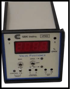
Valve Positioner
INTRODUCTION
We make Valve Position-er is basically an Electronic Instrument intended for continuous Process Control application. This accurate, reliable and Stable instrument is available with input like resistance, mA, mv, etc.Multistage Quality Assurance and Worst Case Proven design resulting in highest Reliability.The miniature design consists of feedback position indication, fault Alarm LED indication for a defect in input Control Signal, and /or feedback Signal.Auto Manual Feature is provided to override control signal in case of control or feedback fault and with the help of open/close signal, we can float the Control Valve to any required position. A current transmission signal is provided to sense Feedback signal for computer, PLC system etc.
FEATURES – Valve Positioner suppliers Valve Positioner suppliers
- Valve Position-er for Single Phase or Three Phase Actuator.
- Feedback Option mA/mV/R
- Valve Positioner suppliers – Re-Transmission Output
- Auto Manual Facility
- Valve Positioner – Compact Versatile Design Valve Positioner suppliers
TECHNICAL SPECIFICATIONS –r suppliers
- Power Supply 230V AC+ -10% 50Hz. Optional 110v AC+-10% 50 Hz PI.Specify
- Control Signal (input) 4-20 mA DC/mV / Resistance (Please Specify)
- Feedback Positioner (For Actuator Position 4-20 mA from 2 Wire Transmitter power supply 24 VDC Built-in
- Feedback Position indication:-
- 3 ½ digit 0.5” height Red LED
- Range 0.0 to 100. 0% open
- Resolution 0.1
- Accuracy 0.2% +-1 digit
- zero, span Adjustable in the range +-10%
- Position Transmission 4-20mA output (self Powered) for DCS/PLC with Load capability 500 Ω max
- Control Features
- Auto/ Manual Selection facility
- Open –OFF – Close Overriding feature with an open/close switch in Manual Mode.
- Xsh-Sensitivity adjustment to avoid Relay chattering.
- Dead band setting provided in front to avoid actuator hunting.Range of adjustment 1 to 10%
- Fault Indication
- If Control Signal absent or less than 4 mA LED glows
- If F.B .Potentiometer open or Wire disconnected Fault LED glows.
- Control/Calibration Adjustments
- Control Signal Zero, Span to match Actuator Travel with Feedback Potentiometer. Location of Front
- Feed Back Pot standardization Zero, Span Potentiometer. Location- On Back Side Right Top
- Indicator adjustment- Zero, Span to adjust % opening Location On front Top
- Sensitivity Pot To avoid relay chattering Location Inside (For Factory set)
- Dead Band Pot To avoid system hunting Adjustment Range 1 to 10% Location On Front
TECHNICAL SPECIFICATION – Valve Positioner suppliers
- Re-transmission Output Adjustment Location – On Back Side Left Bottom
- Size/ Mounting 96*96*125 mm Cut out 92*92 mm Flush Panel Mounting
- Fuse Protection Provided on Back Plate Rating P.S -100 mA, Relay-1 Amp
- Control output Relay contact rated for 5 Amp at 230 V AC resistive load
- Valve Positioner suppliers – Power Consumption 5 VA Max
- Valve Positioner suppliers – Operating Temp 0 – 50°C
- Relative Humidity 90% Rh Max Non –Condensing
- CMRR > 120 db
- NMRR > 80 db
- CMV 500 V DC
- Weight 1 Kg Approximately
- Valve Positioner suppliers – Recommended Calibration Check -1 year Normal 6 months-critical applications
OPERATION – Valve Positioner suppliers
- Single Phase (SP) or Three Phase (TP) Actuator
- Open/off/close of Manual
- Open or Close in Auto Depends on Control & feedback Position-er.Also time delay & dead band Adjustment
- Valve Positioner suppliers – Fault Indication for Control absent “ LED ON “ and Feedback Position-er Fails “LED ON”
APPLICATIONS –
- Valve Positioner suppliers – Controlling Mechanical Position of final control element with respect to incoming
- Valve Positioner suppliers – Command from controllers such as PID/DCS/QCS etc..