
Introduction
This controller, as the name indicates, is used to control the loss plate temperature. It is available in the extruded aluminium enclosure as per DIN standard.
Specifications:
Specifications:
• Input: 2 thermocouple inputs (CR-AL Type)
• Indication: 3.5 digit 7 segment bright red LED display- 2 Nos.
• Resolution: 1˚C
• Indication Accuracy: ±0.5% FSD
• Power Supply: 230V AC ± 10%, 50Hz.
• Linearity: Better than ± 1˚C
• Cold Junction Compensation: Built In
• Break Protection: Upscale
• Reset: Manually for Relay by the Switch on front plate
• Output:
1. Potential free change over contacts rated 1 Amp, 230V resistive loads
2. 0-10V DC proportional to input-2Nos (One for each input)
• Ambient Temperature: 0-50˚C
• Size: 96mmX96mmX150mm (Depth behind panel: 165mm maximum)
Maintenance:
Preventive:
Visual Inspection of Housing, cable connections and clamps should be done once in 3 months to maintain the unit free of abrasive.
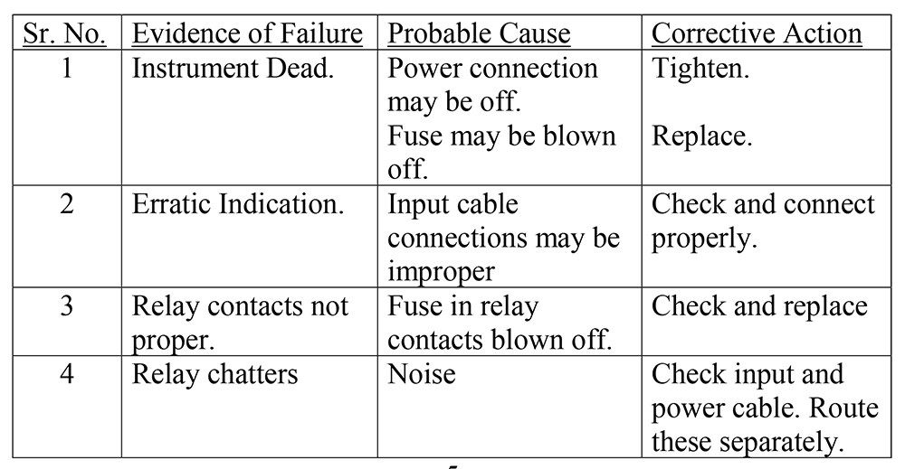
Trouble Shooting:
Trouble Shooting:
Principle of Operation:
The mV output from the thermocouple is amplified by the amplifier. This amplified voltage is then fed to ADC which then uses dual-slope integration technique. ADC indicates the process temperature.
The stable set point voltage is generated using the Zener Diode and multiturn trimpot. The amplified voltage and setpoint voltage is compared by the comparator. This signal is fed to the relay driver circuit. The Relay contacts are manually reset every time by the switch on the front plate.
On the front plate, there are three switches, two multiturn trimpots and one red LED. Using the switch and the multiturn trimpots we can set the required temperature. LED indicates the Relay condition. LED ON means Relay Energized.
When the input is less than the setpoint Relay is energized. If any of the inputs exceeds the corresponding setpoint, Relay is de-energized.
When both the inputs are less than the setpoints, the relay can be energized with the help of the reset switch.
The amplified voltage corresponding to the input is amplified again to get the retransmission output of 0-10V DC of the input. The output voltage is available on the back terminal.
Zero-span calibration for each input and output can be done by the trimpots on the front plate.
Installation and Mounting
1. The instrument is insensitive to mechanical vibrations so it can be installed on machines without experiencing the setting or response changes. The instrument panel is a mounting type.
2. Mount the instrument with the help of the clamps provided.
3. Electrical connections are to be made properly on the backplate. If connections are proper, then switch ON the instrument and allow 30 minutes for thermal stability
References:
1. Box Size: 91mmX91mmX150mm
2. Bezel Size: 96mmX96mmX12mm
3. Depth behind panel: 165mm
4. Panel Mounting: By mounting clamps 2 nos.
5. Panel Cutout: 92mmX92mm